When you click on links to various merchants on this site and make a purchase, this can result in this site earning a commission. Affiliate programs and affiliations include, but are not limited to, the eBay Partner Network.
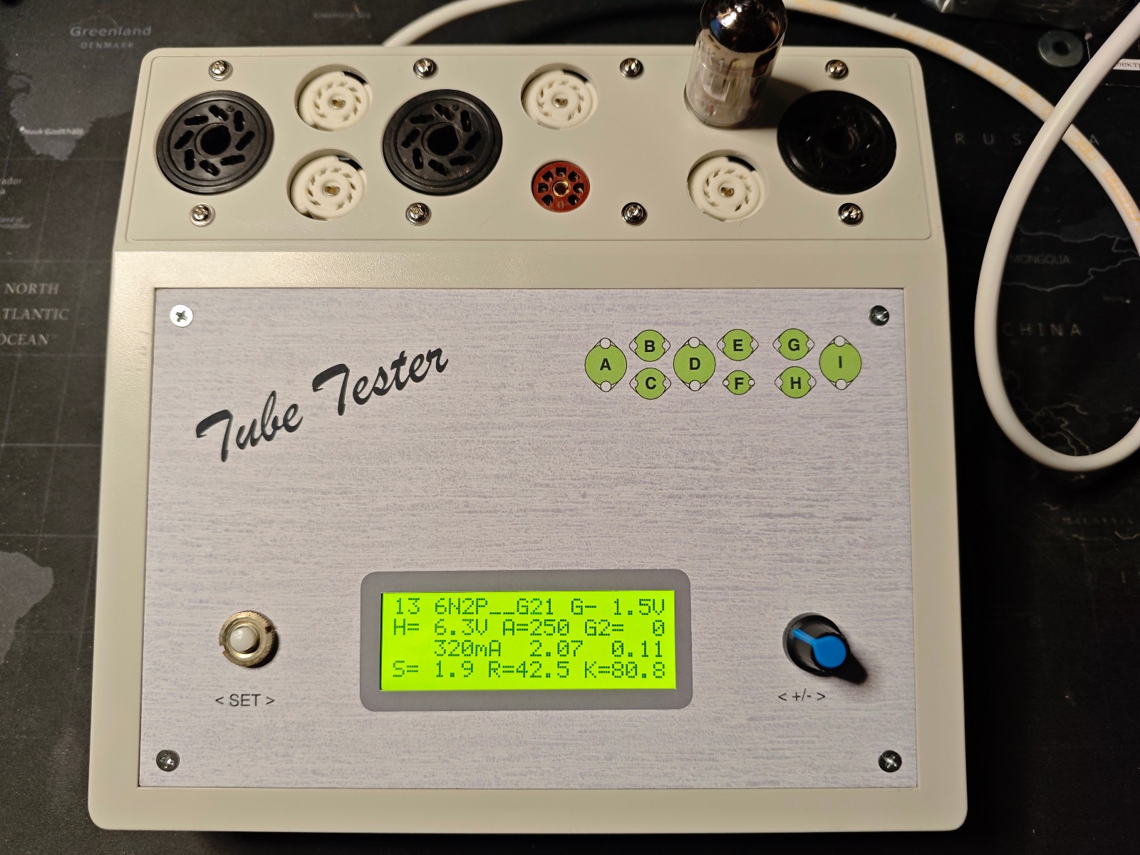
VACUUM TUBE TESTER
Based on the analysis of tube parameters that are currently available and often used, have been specified voltage and current ranges for power supplies:
- heater: 0...15 V / 2.5 A (temporarily to 3 A)
- Ug10...-24 V / 2 mA,
- Ug2/Ig20...300V / 40 mA,
- Ua/Ia0...300 V / 200 mA for increased accuracy in two sub-ranges 20 mA / 200 mA.
235V power supply voltage. Please indicate if you need another supply voltage. The transformer is made to order under your requirements within 1 weeks.
The steepness of the characteristics S (mutual conductance ) is the valueshowing how much the miliamps the anode current of the tube changes when thevoltage changes at the first (control) grid by 1 V with constant voltages onother electrodes. Measured in mA/V. The steepness of the characteristics can bedetermined by the values of the reinforcement coefficient K and theinternal resistance Ri:
S = K/Ri
The internal resistance Ri is the resistanceof the tube to alternating current. It is defined as the ratio of a change in theanode voltage to a change in the anode current with unchanged voltages on otherelectrodes. Measured in kOhm. The internal resistance can be determined by the values of thesteepness of the characteristics of S and the reinforcement coefficient K:
Ri =K/S
The reinforcement coefficient K is anabstract value showing how the voltage change on the first grid affects theanode current compared to the voltage change on the anode. The reinforcementfactor can be determined by the values of the steepness of S and the internalresistance Ri:
K = S*Ri