When you click on links to various merchants on this site and make a purchase, this can result in this site earning a commission. Affiliate programs and affiliations include, but are not limited to, the eBay Partner Network.
Our Restoration Procedures:
1. Check Out The Stereo, If There Is Anything Wrong, We Will Fix It.
2. Clean & Lubricate All Of The Switches & Controls.
3. Electrolytic Capacitor Check, If There Is Any Weak One, We Will Change It.
4. FM IF & MPX Circuit Alignment By Using A Sweep Signal Generator & Victor Scope.
5. Change Burned Lamps.
6. Check Out & Adjust Power Amplifier\'s Center Voltage &StandbyCurrent.
7. Audio Frequency Response & Distortion Test.
8. Clean All Of The Knobs By Ultrasonic Cleaner.
9. Functional Check.
0.All Sales We Give A 90-Day Labor & Parts Warranty, If There Is Any Problem, You Send It Back We Will Repair It For You Free Of Charge, You Pay The Send-In Postage, We Pay The Send-Back Postage.Description
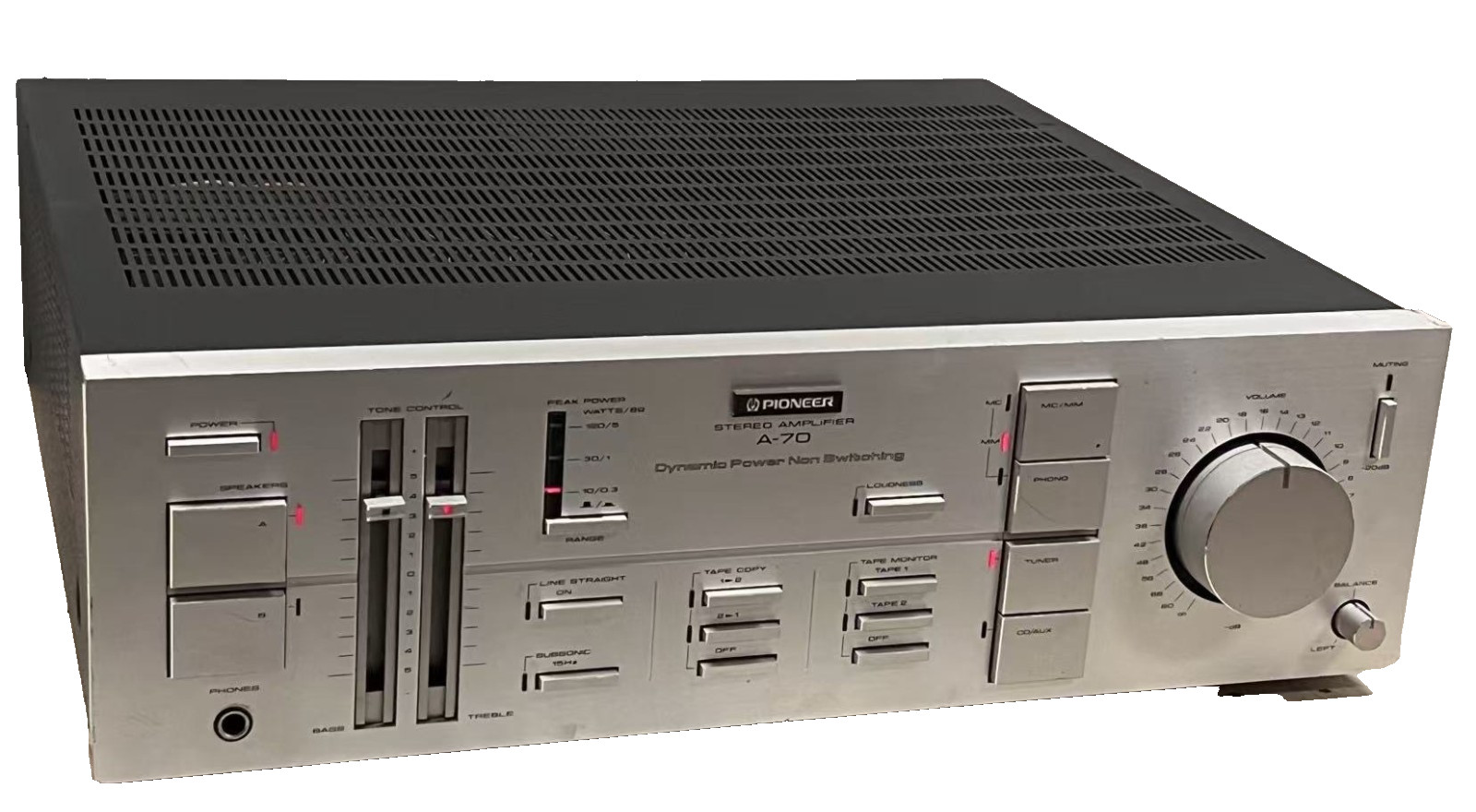
The Pioneer A-70 fulfills the fundamental purpose of an amplifier by faithfully amplifying the music source and driving the speakers without losing any of the original feeling of the music source.
The worst scourge of listening pleasure, the switching problem, has been eliminated by use of the non-switching amplifier system.
The dynamic power supply circuitry has been used in keeping with the expansion of the dynamic range of modern digital audio equipment - this is the dynamic power non-switching that has made quality and high power a reality.
A line straight function which bypasses the tone control and loudness control circuits has been installed.
The simple circuit construction which is so important to sound purity can be easily selected by a flip of the switch.
Peak power values are indicated by three point LED on the highly responsive circuit. A switch has been provided to cope with both low output levels and high output levels.
Careful consideration has been given to the task of fully amplifying the micro signals of the MC cartridge, the most widely used cartridge these days. The first stage uses a low-noise, high-gain FET while the second stage uses a one chip dual operational amplifier. As the signal amplification apparatus and the DC servo amplifier are contained in identical chips, excellent stability is obtained, in practice, a high S/N of 70 dB has been obtained.
The RlAA component, which controls sound quality, consists of a mylar capacitor and a special resistor, while in the DC servo circuit a resin membrane capacitor has been used.
In the power source area which controls sound, the two sides of the large capacity transformer are divided into a power amplifier and a voltage amplifier. Features such as a total 40,000 uF condenser in the power amplifier have been included to produce a strong power source with plenty of extra capacity.
Specifications
Power output: 120 watts per channel into 8Ω (stereo)
Frequency response: 5Hz to 100kHz
Total harmonic distortion: 0.003%
Damping factor: 60
Input sensitivity: 0.2mV (MC), 2.5mV (MM), 150mV (line)
Signal to noise ratio: 70dB (MC), 87dB (MM), 108dB (line)
Output: 150mV (line)
Dimensions: 420 x 131 x 411mm